
rigid flex PCBs used in drone applications
Rigid flex PCBs are used in many applications because they have a combination of rigid and flexible circuit board design features. Rigid areas are designed to accommodate the needs of SMT components while flex sections allow for easy fitting into tight spaces. These hybrid circuit boards can be found in applications that require a combination of space efficiency and durability, including medical imaging equipment, military hardware and aerospace technology. Other industries that often utilize rigid flex circuit boards include automotive electronics and industrial machinery.
Drones and UAV (unmanned aerial vehicles) are operated in environments with high vibration levels that can damage or destroy electronic devices. Rigid flex PCBs have the ability to withstand these harsh conditions because of their hybrid structure and robustness. These types of circuit boards offer dependable performance while optimizing the space inside of drone and UAV devices. Additionally, rigid flex PCBs are able to shield motors and other devices from electromagnetic interference that can interfere with video feeds.
Additionally, rigid flex pcb are lightweight and can decrease the weight of UAVs to increase energy efficiency. The rigid flex PCB’s hybrid structure also offers high shock resistance, which is critical for drone and aviation equipment. Additionally, this type of circuit board can be customized with a variety of features and processes that can benefit the design, operation, or maintenance of the device.
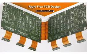
How are rigid flex PCBs used in drone applications?
When designing a rigid-flex PCB, it’s important to ensure that the design is as efficient as possible. This will help reduce costs and improve time-to-market for the final product. This can be accomplished by ensuring that the PCB has the right layer count, material selection and layout. Additionally, implementing proper design practices will also reduce the likelihood of errors during manufacturing and assembly.
One of the most important elements when creating a rigid-flex PCB is making sure that the signal layers are properly transitioned from the rigid to the flexible portion of the circuit board. This is essential because improper layer transitions can result in impedance mismatches and signal degradation. Additionally, a rigid-flex circuit board will need to be fabricated with thermal management in mind because the bending and flexibility of the flex sections can cause heat to build up in the board.
To avoid these issues, it’s recommended to have a team of design and engineering professionals work together to create the circuit board. This will help prevent potential errors and make it easier for the manufacturer to produce a high-quality, reliable board. Additionally, the manufacturer should have the capability to prototype and test rigid-flex PCBs before mass production. This will help to avoid any costly mistakes during production and minimize the risk of production delays.
When designing a rigid-flex PCB, designers should use an integrated MCAD and ECAD software program that allows them to view the bending regions of the circuit board in 3D. This will help them design the right packaging for their application. It’s also important to consider the manufacturing and assembly process for the rigid-flex PCB before deciding on a design. This will help to reduce manual routing time and improve the reliability of the final product.
